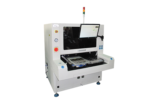
Introduction to the production process
1. Exit the platform and manually put the FPC on
2. Manually fix the soft board product to the workbench, open the vacuum on the upper and lower workbenches, and the soft board will be firmly and flatly adsorbed on the platform;
3. Manually place the film on the upper platform and press the start button;
4. The upper and lower worktables have a rough positioning controlled by a cylinder (motor), the lower worktable enters the mounting range, and the upper worktable descends, so that the distance between the two worktables is reduced to 1-2mm;
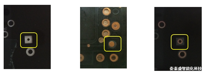
5. Machine vision detects whether the circles of the upper and lower platforms coincide, and controls X, Y, R compensation and correction;
6. After OK, the Z-axis is lowered to press the negative film and the soft board to make them re-bonded;
7. The Z axis rises and the lower platform exits;
8. The operator removes the finished product for the next cycle.

�Description of visual alignment principle:
After the mechanical rough positioning is 1.5mm, the upper CCD is used to grab the center of the small circle on the negative and the large circle on the FPC, and the process controls the three-axis compensation of X, Y, and U to achieve the coincidence of the two circle centers, and then the Z axis slowly descends. The CCD takes pictures continuously to control the motor correction. Final press.

Upper platform structure description:
1). The structure of the upper platform is a large suction cup, Z-axis coarse positioning, Z-axis high-precision positioning, U-axis (angle), 3 sets of single-cylinder CCD + microscope (one set is reserved for inspection)
2). The suction cup is a suction head made of the whole piece of precision plane processing to ensure that the negative film will not be deformed after suction;
3.) The Z-axis drive suction cup wirelessly approaches the lower platform, and the distance software is adjustable;
4). Machine vision detects whether the center of the upper and lower materials coincides;
5). The U-axis is driven by a private service motor, and the small wheel drives the belt structure of the large wheel to ensure that the deviation of the angle is small;
6). When it is visually found that the two centers of circles coincide, press down and fit, and the upper platform is provided with a spring for buffering;
7). Coarse positioning is controlled by motor or cylinder.
Lower platform structure description:
- The suction cup is a suction head made of a whole piece of precision plane processing to ensure that the adsorbed soft board will not be deformed;
-The platform enters and exits under the control of the cylinder and realizes rough positioning;
-X and Y are controlled by high precision motor and precision small lead screw;
Measures to ensure accuracy:
- The upper and lower attached platforms must be specially
Processed to ensure flatness;
-Using the full loop visual detection, the vision is not only shot once, but continuously shot and corrected. That is, every time the height drops a little, detect the X, Y offset, the angle offset, and then adjust, then drop a little bit, and then fix it - positive, until it fits completely;
-U-axis is driven by servo motor, the small wheel drives the belt structure of the large wheel to ensure that the deviation of the angle is small, and the belt pulley is a belt-driven mechanism without gaps;
-X, Y, Z screw rods are precision dedicated screw guide rails with small lead, such as lead 1mm, etc.;
- The upper and lower nozzle planes must be precisely adjusted to be parallel.


